Flame Sensor Module: Working Principle, Pinout, Circuit Diagram, and Applications
Overview
Introduction
Fire is one of the most dangerous hazards in both homes and industries. Detecting fire at the right time can prevent huge damage and save lives. For this purpose, special electronic devices are used, and one of the most common and effective ones is the Flame Sensor.
A flame sensor is a small electronic module designed to detect the presence of fire or flame within its sensing range. It works by identifying the light waves emitted by fire and then producing an electrical signal. This signal can be used to activate alarms, safety systems, or other automatic equipment. Because of its accuracy, low cost, and fast response, flame sensors are widely used in fire detection circuits and fire alarm systems. In this article, we will discuss everything about flame sensors, including their working principle, pinout details, features, types, advantages, limitations, applications, and even a practical example.What is a Flame Sensor?
A flame sensor is an electronic component that can sense infrared light emitted by fire. Whenever a flame is present in front of it, the sensor produces an output signal that can be used to trigger safety devices. The main purpose of this sensor is to give an early warning of fire so that preventive actions can be taken immediately. The flame sensor module is generally compact and easy to use. It can be connected to simple circuits or microcontrollers like Arduino, STM32, or PIC. Because of its versatility, it is suitable for both beginners learning electronics and professionals building safety equipment.Working Principle of Flame Sensor
The working of a flame sensor is based on infrared light detection. When a flame burns, it produces infrared radiation in a specific wavelength range, generally between 760 nm and 1100 nm.
- The flame sensor has a photodiode or phototransistor that reacts to this radiation.
- When no flame is present, the sensor output remains low.
- When a flame is present, the radiation changes the sensor’s resistance, and the output pin generates a signal.
-
Digital Output (DO): Gives HIGH or LOW signals depending on the flame.
-
Analog Output (AO): Provides a voltage proportional to the intensity of the flame.
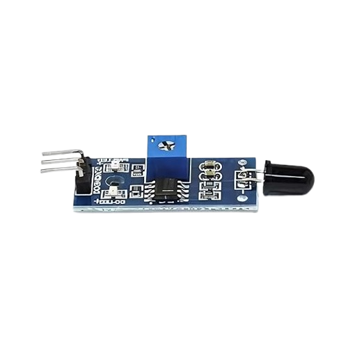
Flame Sensor Pinout
A typical flame sensor module comes with three pins:
-
VCC – Power supply pin, usually 3.3V to 5V.
-
GND – Ground pin.
-
OUT – Output signal pin.
Some modules may also have DO (digital output) and AO (analog output) separately, along with a sensitivity adjustment knob.
Circuit of Flame Sensor
The basic connection of a flame sensor is very simple.- Connect the VCC pin to 5V supply.
- Connect the GND pin to ground.
- Connect the OUT pin to an input of a microcontroller or a transistor.
- Use an LED or buzzer as an indicator.
Features of Flame Sensor
Some common features of flame sensors include:- Operating Voltage: 3.3V to 5V
- Wavelength Sensitivity: 760 nm to 1100 nm
- Detection Range: up to 100 cm (depending on flame size)
- Adjustable sensitivity (in some modules)
- Digital and analog outputs available
- Compact, lightweight, and affordable
- Quick response time
Types of Flame Sensors
Flame sensors are available in different types depending on their technology:-
Infrared (IR) Flame Sensor
- Detects IR light emitted by fire.
- Low cost and easy to use.
- Suitable for small projects and alarms.
-
Ultraviolet (UV) Flame Sensor
- Detects UV radiation produced during combustion.
- Commonly used in gas flame monitoring.
-
UV-IR Combined Sensor
- Uses both UV and IR detection.
- Reduces false alarms caused by sunlight or lamps.
- More reliable than single-type sensors.
-
IR3 (Triple Infrared) Sensor
- Uses three different IR wavelength bands for detection.
- Very accurate and commonly used in industrial fire safety systems.
Advantages of Flame Sensor
- Provides early fire detection.
- Works quickly with high sensitivity.
- Compact and portable.
- Easy integration with different circuits.
- Low power consumption.
- Can detect fire even from a distance.
Limitations of Flame Sensor
- Limited detection range compared to advanced systems.
- May produce false alarms if exposed to strong IR sources like sunlight.
- Needs proper placement and calibration.
- Environmental factors like smoke or dust may reduce accuracy.
Applications of Flame Sensor
Flame sensors are widely used in different areas, including:- Fire alarm systems in homes and offices.
- Automatic fire extinguishing systems.
- Gas leakage and fire detection equipment.
- Safety devices in industries and factories.
- Fire detection in vehicles and aircraft.
- Educational projects and laboratory experiments.
Example: Flame Sensor with LED and Buzzer Alarm
Components Required:
- Flame Sensor Module
- Transistor (e.g., BC547)
- LED and Buzzer
- Resistors
- Power Supply (5V)
Circuit Description:
- Connect VCC of the flame sensor to 5V supply.
- Connect GND to the negative terminal.
- Connect OUT pin to the base of a transistor through a resistor.
- Connect the buzzer and LED to the transistor’s collector.
Working:
- When no flame is present, the sensor output is LOW, keeping the transistor OFF, so LED and buzzer remain OFF.
- When a flame is detected, the sensor output goes HIGH, turning ON the transistor.
- The transistor activates the LED and buzzer, giving a clear fire warning.
Conclusion
Flame sensors are simple yet powerful devices that play a crucial role in safety and protection systems. They are designed to detect fire quickly and provide an electrical signal that can be used for alarms, automatic systems, or emergency responses.Where to Buy
Prices may vary. Click on "Buy Now" to check current availability and pricing.
Administrator
Frequently Asked Questions
Common questions about Flame Sensor Module: Working Principle, Pinout, Circuit Diagram, and Applications. Find answers to the most frequently asked questions.
User Reviews & Comments
Share your experience with this IoT Blog. Your feedback helps our community make informed decisions!
Share Your Experience
Help others by sharing your thoughts about this IoT Blog.
Related Blogs
Explore more IoT Blogs in the same category
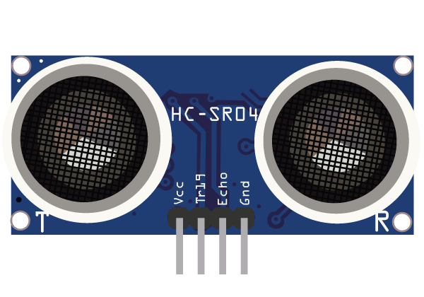
Ultrasonic Sensor HC-SR04 for IoT: Working, Applications, Circuit, and Integration Guide
Sensors
Discover how the Ultrasonic Sensor HC-SR04 works and how to use it in IoT projects. This detailed guide covers its working principle, pin configuration, interfacing with Arduino, applications in smart systems, and complete circuit setup. Ideal for beginners and IoT developers looking to integrate distance sensing in real-time projects.
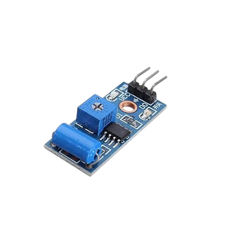
Vibration Sensor: Working, Types, Applications, and Complete Guide
Sensors
A vibration sensor is a crucial device used to detect and measure vibrations in machines, structures, and environments. This complete guide covers how vibration sensors work, their different types, applications across industries, and factors to consider before selection. Learn how these sensors improve safety, enhance performance, and prevent costly equipment failures.
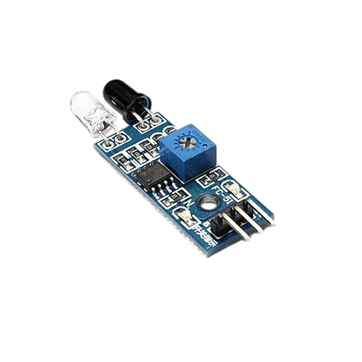
Best IR Sensor for IoT Projects – Types, Working, Interfacing, and Applications Explained
Sensors
Discover everything about IR sensors used in modern IoT applications. Learn their types, working principles, interfacing methods, and real-world uses. This complete guide helps developers and engineers choose the best IR sensor for smart electronics and automation projects with reliable performance.
No Reviews Yet
Be the first to share your experience with this IoT Blog!