Joystick Module for IoT: Types, Working, Pinout, Interfacing, and Applications Explained
Overview
Introduction
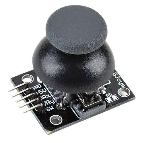
Joystick Module is one of the most essential input devices used in modern IoT projects, especially for robotics, remote-controlled vehicles, and smart automation systems. It is an analog sensor that allows you to detect motion in two axes (X and Y) and sometimes includes a push-button feature as well. Whether you're a hobbyist building a robotic arm or a student developing a wireless car, a Joystick Module gives you intuitive control over your device.
In this comprehensive guide, we’ll cover everything you need to know about the Joystick Module, including its types, internal working, pin configuration, interfacing with Arduino, and real-world IoT applications.
What is a Joystick Module?
A Joystick Module is an analog input device used to provide directional input to microcontrollers like Arduino, ESP32, or Raspberry Pi. It contains two potentiometers (for X and Y axis) and a momentary push button (Z-axis) to detect directional movement and clicks. It is widely used in gaming controllers, robotics, and IoT control systems.
Internal Working of Joystick Module
The Joystick Module works on the principle of voltage division using two potentiometers:
-
X-axis potentiometer changes resistance when moved horizontally.
-
Y-axis potentiometer changes resistance when moved vertically.
-
When the joystick is moved, it generates analog voltage signals (0V to 5V), which are read by the microcontroller's ADC (Analog-to-Digital Converter).
- Pressing the joystick button connects the SW (switch) pin to GND, which can be detected as LOW (0).
Pinout of Joystick Module
| Pin Name | Description |
|---|---|
| GND | Ground |
| +5V | Power Supply (Usually 5V) |
| VRx | X-axis Analog Output |
| VRy | Y-axis Analog Output |
| SW | Switch Output (Button Press) |
Technical Specifications
-
Operating Voltage: 3.3V to 5V
-
Output Type: Analog (VRx, VRy), Digital (SW)
-
Axes Supported: X, Y (with Z as push-button)
-
Push Button Type: Momentary
-
Size: Compact and breadboard friendly
-
Power Consumption: Low
Types of Joystick Modules
Joystick Modules come in different variants based on features and application:-
Analog Joystick Module
- Basic 2-axis joystick with push-button.
- Suitable for Arduino-based projects.
-
Digital Joystick Module
- Offers digital HIGH/LOW output instead of analog.
- Ideal for microcontrollers without ADC.
-
Thumb Joystick
- Smaller size, used in compact devices or gaming systems.
-
Industrial Joystick
- Rugged and heavy-duty, used in real industrial control systems.
Applications of Joystick Module in IoT
-
Smart Robot Control
-
Wireless Wheelchair Navigation
-
Remote-controlled Vehicles
-
Pan-Tilt Camera Systems
-
Gesture-Based IoT Devices
-
Game Console Interfaces
-
Home Automation Panels
Interfacing Joystick Module with Arduino (Example)
Required Components:
- Arduino Uno/Nano
- Joystick Module
- Jumper Wires
- Breadboard (optional)
Circuit Connection:
| Joystick Pin | Arduino Pin |
|---|---|
| GND | GND |
| +5V | 5V |
| VRx | A0 |
| VRy | A1 |
| SW | D2 |
Arduino Code Example:
Output:
When you move the joystick:-
X and Y values vary from 0 to 1023
-
When button is pressed, output shows “Button: Pressed”
Tips for Using Joystick Module in IoT Projects
-
Use analog pins with ADC resolution (10-bit recommended)
- Debounce the button using software or external resistor if needed
-
Apply low-pass filtering for smoother motion control
- Calibrate X and Y ranges for precision in sensitive projects
-
Add wireless modules like nRF24L01, ESP8266, or Bluetooth HC-05 for remote joystick control
Where to Buy
Prices may vary. Click on "Buy Now" to check current availability and pricing.
Administrator
Frequently Asked Questions
Common questions about Joystick Module for IoT: Types, Working, Pinout, Interfacing, and Applications Explained. Find answers to the most frequently asked questions.
User Reviews & Comments
Share your experience with this IoT Blog. Your feedback helps our community make informed decisions!
Share Your Experience
Help others by sharing your thoughts about this IoT Blog.
Related Blogs
Explore more IoT Blogs in the same category
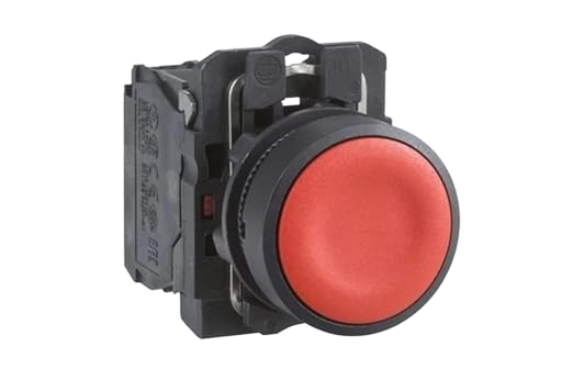
Push Button in IoT: Working, Applications & Wiring Explained
Input Devices
Learn everything about Push Buttons in IoT devices, including their working, wiring techniques, and real-time applications. This detailed guide helps electronics beginners and developers understand how push buttons are used in smart systems. Perfect for IoT-based projects and educational use. Discover how this small component plays a big role in modern automation.
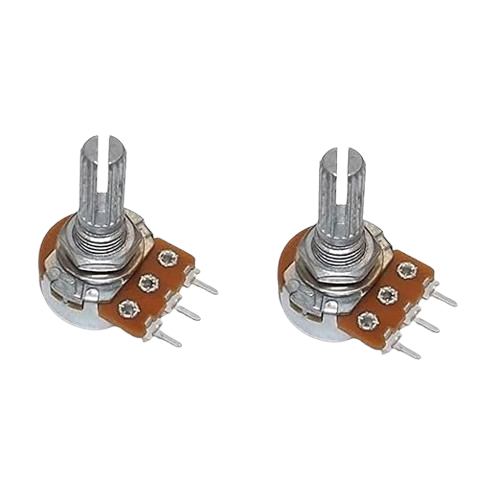
Potentiometer: Types, Working Principle, Applications, Advantages & Selection Guide
Input Devices
A potentiometer is a three-terminal variable resistor used to control voltage and current in electronic circuits. This detailed guide explains potentiometer types, working principle, applications, and benefits, along with tips for choosing the right one. Perfect for students, hobbyists, and professionals seeking clear, accurate, and practical information.
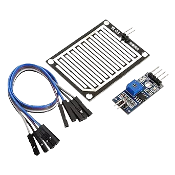
Rain Sensor in IoT: Working, Applications, and Benefits Explained
Input Devices
A rain sensor is a smart device used to detect rainfall and automate responses in various systems. It plays an important role in IoT by enabling weather monitoring, smart irrigation, and water conservation. This technology improves efficiency, reduces wastage, and supports modern applications in agriculture, home automation, and environmental monitoring.
No Reviews Yet
Be the first to share your experience with this IoT Blog!