MPU-6050 Sensor: Features, Working, Pinout, Applications, and Example Code
Overview
Introduction
The MPU-6050 is one of the most widely used motion sensors in electronics and embedded systems. It combines a 3-axis accelerometer and a 3-axis gyroscope into a single compact chip, giving it the ability to measure both linear acceleration and angular velocity. This makes it a 6-axis motion tracking device. The sensor also includes a built-in Digital Motion Processor (DMP) that helps in handling complex calculations directly inside the chip, reducing the processing load on the main controller. Because of its high accuracy, small size, and low cost, the MPU-6050 is used in many fields such as robotics, drones, gaming devices, and smartphones. Whether you are a student, hobbyist, or professional developer, this sensor provides an excellent solution for motion sensing and orientation measurement.Features of MPU-6050
The popularity of the MPU-6050 is due to the powerful features it offers:-
6-axis sensing capability: 3-axis accelerometer and 3-axis gyroscope in one chip.
-
Built-in Digital Motion Processor (DMP): Processes sensor data internally and reduces the load on the microcontroller.
-
Wide measuring ranges:
- Accelerometer: ±2g, ±4g, ±8g, ±16g
- Gyroscope: ±250°/s, ±500°/s, ±1000°/s, ±2000°/s
-
High resolution: 16-bit ADC for precise data output.
-
Low power consumption: Ideal for portable and battery-operated devices.
-
Operating voltage: 3.3V to 5V when used with breakout modules.
-
Built-in temperature sensor for additional measurements.
-
Compact package: 4 × 4 × 0.9 mm QFN, making it suitable for small devices.
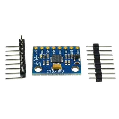
Pinout of MPU-6050
The MPU-6050 chip usually comes mounted on a breakout board, making it easier to connect with a microcontroller. The common pin configuration is as follows:-
VCC: Power supply (3.3V or 5V).
-
GND: Ground connection.
-
SCL: Serial Clock Line for I²C communication.
-
SDA: Serial Data Line for I²C communication.
-
XDA: Auxiliary data line (used when connecting other sensors).
-
XCL: Auxiliary clock line.
-
AD0: I²C address selection (used to connect multiple devices on the same bus).
-
INT: Interrupt pin, useful for detecting motion events.
Working Principle
The MPU-6050 measures both acceleration and rotation:-
Accelerometer: Detects linear acceleration in the X, Y, and Z directions. It helps in finding tilt, orientation, and movement.
-
Gyroscope: Measures angular velocity, i.e., how fast the device is rotating around the X, Y, and Z axes.
-
Digital Motion Processor (DMP): A built-in unit that processes raw accelerometer and gyroscope data, filters noise, and provides more stable results.
Technical Specifications
-
Supply Voltage: 2.3V – 3.4V (with breakout boards supporting 3.3V and 5V).
-
Gyroscope Range: ±250°/s, ±500°/s, ±1000°/s, ±2000°/s.
-
Accelerometer Range: ±2g, ±4g, ±8g, ±16g.
-
Output Resolution: 16-bit data.
-
Communication: I²C up to 400 kHz, SPI support in some variants.
-
Built-in Temperature Sensor: Available for additional use.
Applications of MPU-6050
Thanks to its accurate sensing and compact size, the MPU-6050 is used in many practical areas:- Drones and quadcopters for stabilization.
- Robotics for motion and orientation control.
- Smartphones for screen rotation and gaming controls.
- Wearable devices for fitness tracking.
- Virtual reality and augmented reality systems.
- Motion-based gaming consoles.
- Gesture recognition systems.
- Automotive systems for safety and navigation.
Variants and Similar Sensors
The MPU-6050 has some related sensors and upgraded models that expand its capabilities:-
MPU-6000: Similar to MPU-6050 but with better SPI support.
-
MPU-6500: Improved power efficiency and performance.
-
MPU-9150: Combines accelerometer, gyroscope, and magnetometer (9-axis).
-
MPU-9250: Advanced 9-axis sensor with better calibration features.
Interfacing MPU-6050 with Arduino
The most common way to use the MPU-6050 is through the I²C interface. The steps are:-
Connect VCC to 3.3V or 5V and GND to ground.
-
Connect SCL and SDA to the respective pins on Arduino (A5 and A4 for Arduino Uno).
- Initialize the sensor by writing to its power management register.
- Read accelerometer and gyroscope data registers.
- Convert the raw values into meaningful physical units.
Example Arduino Code for MPU-6050
Conclusion
The MPU-6050 is a powerful yet affordable motion tracking sensor that provides both accelerometer and gyroscope data in a single chip. Its wide measuring range, easy interfacing through I²C, and built-in Digital Motion Processor make it suitable for a variety of applications such as drones, robotics, smartphones, and gaming devices. With many variants available, it offers flexibility for different levels of projects, from basic motion detection to advanced 9-axis tracking systems. By learning how to connect and program the MPU-6050, developers and students can unlock a wide range of motion-based applications. Its combination of simplicity and accuracy has made it one of the most reliable sensors in the world of electronics.Where to Buy
Prices may vary. Click on "Buy Now" to check current availability and pricing.
Administrator
Frequently Asked Questions
Common questions about MPU-6050 Sensor: Features, Working, Pinout, Applications, and Example Code. Find answers to the most frequently asked questions.
User Reviews & Comments
Share your experience with this IoT Blog. Your feedback helps our community make informed decisions!
Share Your Experience
Help others by sharing your thoughts about this IoT Blog.
Related Blogs
Explore more IoT Blogs in the same category
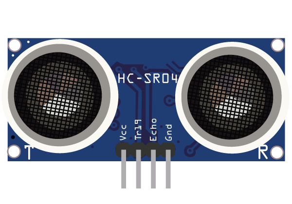
Ultrasonic Sensor HC-SR04 for IoT: Working, Applications, Circuit, and Integration Guide
Sensors
Discover how the Ultrasonic Sensor HC-SR04 works and how to use it in IoT projects. This detailed guide covers its working principle, pin configuration, interfacing with Arduino, applications in smart systems, and complete circuit setup. Ideal for beginners and IoT developers looking to integrate distance sensing in real-time projects.
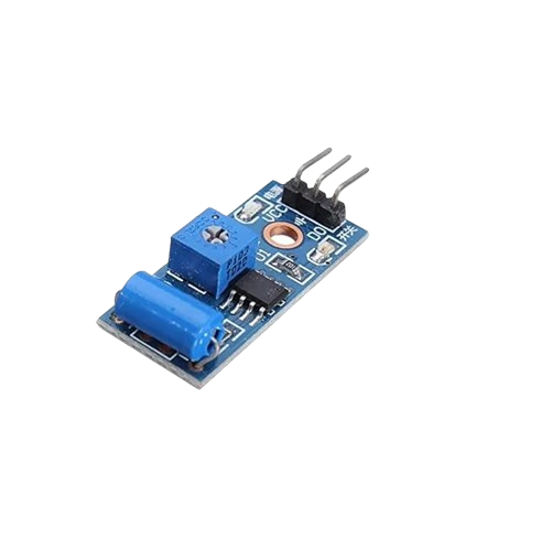
Vibration Sensor: Working, Types, Applications, and Complete Guide
Sensors
A vibration sensor is a crucial device used to detect and measure vibrations in machines, structures, and environments. This complete guide covers how vibration sensors work, their different types, applications across industries, and factors to consider before selection. Learn how these sensors improve safety, enhance performance, and prevent costly equipment failures.
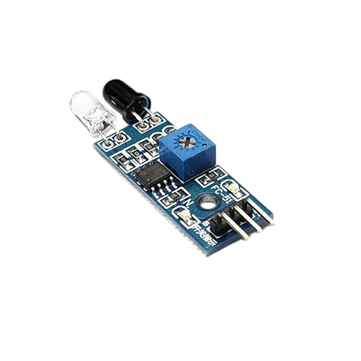
Best IR Sensor for IoT Projects – Types, Working, Interfacing, and Applications Explained
Sensors
Discover everything about IR sensors used in modern IoT applications. Learn their types, working principles, interfacing methods, and real-world uses. This complete guide helps developers and engineers choose the best IR sensor for smart electronics and automation projects with reliable performance.
No Reviews Yet
Be the first to share your experience with this IoT Blog!