RGB 3 Color LED Module: Working Principle, Pinout, Circuit Diagram and Applications
Overview
Introduction
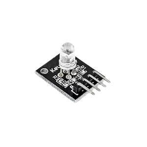
The RGB 3 Color LED Module is one of the most useful and fascinating components in electronics. It allows us to generate multiple colors of light using just three LEDs – red, green, and blue. By mixing these colors in different brightness levels, you can produce almost any shade you want. This makes the RGB module perfect for learning electronics, building DIY projects, or even creating decorative lighting systems. In this guide, we will explore everything about the RGB 3 Color LED Module – from its working principle and pinout details to different types, circuit connections, practical examples, and real-world applications.What is an RGB 3 Color LED Module?
An RGB 3 Color LED Module is a small electronic board that has three LEDs in one package: a red LED, a green LED, and a blue LED. Each LED can be turned on or off individually, and when combined, they can create many different colors. For example:- If only the red LED is on, you see red light.
- If the red and green LEDs are on together, the light looks yellow.
- If all three are on at the same time, you get white light.
This happens because of the additive color mixing principle, where combining primary colors (red, green, and blue) in different intensities results in new colors.
Working Principle of RGB LED Module
The concept behind the RGB module is very simple but powerful. Each LED inside the module represents a primary color. By controlling the brightness of each LED, you can make countless color combinations.-
Red + Green = Yellow
-
Red + Blue = Magenta
-
Green + Blue = Cyan
-
Red + Green + Blue = White
If you lower or increase the intensity of any LED, the shade changes. This is usually done using PWM (Pulse Width Modulation) signals from a microcontroller.
Pinout of RGB 3 Color LED Module
Most RGB 3 Color LED Modules have four pins:-
R Pin (Red) – Controls the red LED
-
G Pin (Green) – Controls the green LED
-
B Pin (Blue) – Controls the blue LED
-
Common Pin – Shared pin (either connected to VCC or GND)
-
Common Cathode: All cathodes (negative ends) are connected together to ground. You supply positive signals to each LED.
-
Common Anode: All anodes (positive ends) are connected together to VCC. You control each LED by grounding the cathodes.
Features of RGB 3 Color LED Module
- Compact and lightweight design
- Works on low voltages (typically 3.3V to 5V)
- Can generate millions of colors by mixing RGB values
- Easy to interface with microcontrollers like Arduino, STM32, PIC, or Raspberry Pi
- Long lifespan and reliable operation
- Energy efficient compared to traditional lamps
Types of RGB LED Modules
RGB LED Modules are available in a few different designs depending on usage:-
3-Pin RGB Modules
- Combine R, G, and B into three control pins with a built-in common pin.
- Usually used for simple circuits.
-
4-Pin RGB Modules
- Provide separate pins for R, G, and B with one common pin.
- More flexible and commonly used in projects.
-
Digital RGB Modules (with IC)
- Include a built-in driver IC such as WS2812.
- Can be chained together and controlled individually using serial data.
- Used in advanced lighting and display projects.
Circuit Diagram and Connection
To use an RGB 3 Color LED Module, you need to connect it properly in a circuit.-
Connect a resistor (typically 220Ω or 330Ω) in series with each LED pin to limit current.
-
For a common cathode module, connect the common pin to GND.
-
For a common anode module, connect the common pin to VCC.
- Connect the R, G, and B pins to microcontroller output pins (preferably PWM pins).
Example Project: RGB Module with Arduino
Let’s look at a practical example using Arduino.Connections:
- R Pin → Arduino Pin 9
- G Pin → Arduino Pin 10
- B Pin → Arduino Pin 11
- Common Pin → GND (for common cathode)
Code Example:
This program cycles through different colors one after another. By changing the values in setColor(), you can generate any custom color.
Applications of RGB 3 Color LED Module
The RGB module is used in a wide range of electronics and lighting projects. Some common applications include:
-
Decorative lighting in homes, cars, and parties
-
Digital displays and advertising boards
-
Status indicators in electronic devices
-
DIY projects for students and hobbyists
-
Learning projects to understand color theory and microcontroller programming
-
Stage lighting and effects for events and shows
-
Prototyping in educational labs
Advantages of RGB LED Module
- Simple to use and affordable
- Generates a wide variety of colors
- Easy to integrate with controllers
- Energy efficient and long-lasting
- Compact design suitable for small projects
- Available in multiple versions for different needs
Practical Example of Color Mixing
To understand how flexible the RGB module is, imagine you want to create a soft pink color. You can do this by turning on:
- Red LED at high brightness (200–255)
- Green LED at low brightness (50–80)
- Blue LED at medium brightness (100–150)
The result will be a pink shade. Similarly, by experimenting with values, you can design any color you like.
Conclusion
The RGB 3 Color LED Module is a small but powerful electronic component that brings endless possibilities in lighting and electronics projects. It works on a simple principle of mixing red, green, and blue light, yet it can produce millions of colors. With its compact design, low power usage, and wide range of applications, it is a must-have for anyone learning electronics or working on creative projects. Whether you are building a colorful display, an indicator light, or a DIY experiment, the RGB 3 Color LED Module will make your project both functional and visually impressive.
Where to Buy
Prices may vary. Click on "Buy Now" to check current availability and pricing.
Administrator
Frequently Asked Questions
Common questions about RGB 3 Color LED Module: Working Principle, Pinout, Circuit Diagram and Applications. Find answers to the most frequently asked questions.
User Reviews & Comments
Share your experience with this IoT Blog. Your feedback helps our community make informed decisions!
Share Your Experience
Help others by sharing your thoughts about this IoT Blog.
Related Blogs
Explore more IoT Blogs in the same category
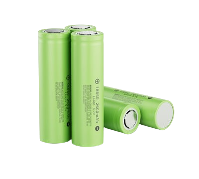
Li-ion Batteries for IoT: Maximizing Performance, Longevity, and Efficiency
Power Supply
Dive deep into the world of Li-ion batteries tailored for IoT applications. This detailed resource covers everything from fundamental principles to advanced optimization techniques. Understand how to choose the right battery, extend device runtime, and enhance overall system reliability, all crucial for your connected innovations.
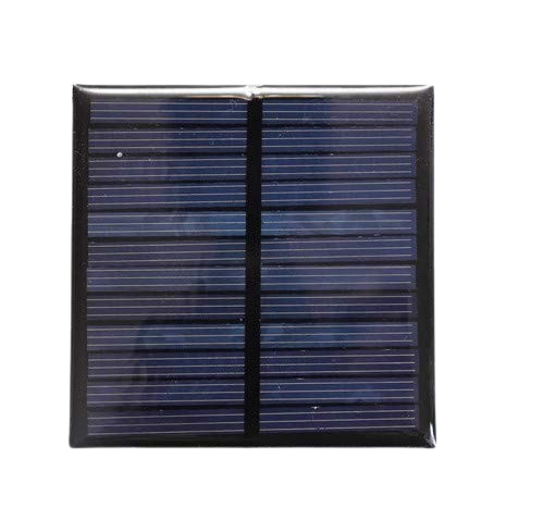
Solar Panel: Types, Benefits, Installation Cost, and Maintenance Guide for Home & Commercial Use (2025)
Power Supply
Discover everything about solar panels in this complete guide covering types, benefits, installation cost, and maintenance tips. Whether you're planning for home or commercial use, learn how solar energy can reduce your electricity bills and promote sustainability. Ideal for beginners and property owners exploring solar power solutions in 2025.
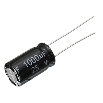
Capacitors: Types, Working, Applications, Selection Guide & Complete Technical Overview
Power Supply
Discover everything about capacitors in this complete technical guide. Learn capacitor types, working principles, real-world applications, and how to choose the right one for your circuit. Ideal for students, engineers, and electronics enthusiasts seeking reliable, accurate information
No Reviews Yet
Be the first to share your experience with this IoT Blog!