Ultimate Guide to Relay Modules for IoT: Complete Details and Setup Tips
Overview
Relay modules are indispensable components in the world of Internet of Things (IoT) and smart automation. They act as electrically operated switches, bridging the gap between low-power IoT devices and high-power electrical appliances. Whether you're automating your home, controlling industrial machinery, or building a smart city solution, understanding relay modules is key to creating efficient, reliable, and scalable IoT systems. This comprehensive guide explores relay modules in detail, covering their features, types, applications, setup, specifications, wiring techniques, and a practical example to help you master their use in IoT projects.
What Are Relay Modules?
A relay module is an electronic component that uses an electromagnet to mechanically open or close an electrical circuit. In IoT applications, relay modules allow low-power signals from microcontrollers (like Arduino, Raspberry Pi, or ESP32) to control high-power devices such as lights, motors, or appliances. They serve as a safe interface, isolating sensitive IoT components from high-voltage circuits to prevent damage.
Key Features of Relay Modules
-
High-Power Control: Manage devices operating at 120V–240V AC or high-current DC circuits using low-power signals (3.3V–5V).
-
Isolation: Opto-isolated designs protect microcontrollers from high-voltage surges.
-
Versatility: Available in single-channel (1 relay) to multi-channel (up to 16 relays) configurations.
-
Ease of Use: Pre-built modules with screw terminals and header pins simplify connections.
-
Compatibility: Works with popular IoT platforms like Arduino, Raspberry Pi, ESP8266, and ESP32.
-
Cost-Effective: Affordable, with modules starting as low as $2–$5 on platforms like Amazon.
Types of Relay Modules
Relay modules come in various types to suit different IoT applications. Choosing the right type depends on your project’s requirements, such as load type, switching frequency, and environment. Below are the primary types:1. Electromechanical Relays (EMR)
-
Description: Use an electromagnet to physically move a metal contact to open or close a circuit.
-
Pros: High current/voltage handling (up to 250V AC, 30V DC, 10A–30A), cost-effective, widely available.
-
Cons: Mechanical wear, slower switching speed, audible clicking noise.
-
Use Cases: Home automation (lights, fans), industrial motor control.
2. Solid-State Relays (SSR)
-
Description: Use semiconductor devices (like transistors or MOSFETs) instead of mechanical parts to switch circuits.
-
Pros: Faster switching, silent operation, longer lifespan, no mechanical wear.
-
Cons: Higher cost, heat generation, limited to specific voltage/current ranges.
-
Use Cases: High-frequency switching, temperature control systems, IoT-based HVAC.
3. Reed Relays
-
Description: Use a magnetic field to close a sealed glass tube containing metal contacts.
-
Pros: Compact, low power consumption, fast switching.
-
Cons: Limited current/voltage capacity (typically <1A, <100V).
-
Use Cases: Low-power IoT sensors, medical devices.
4. Smart Relays
-
Description: Advanced relays with integrated sensors, microcontrollers, and communication modules (Wi-Fi, Bluetooth, RS485).
-
Pros: Remote monitoring, predictive maintenance, AI/ML integration for real-time decision-making.
-
Cons: Complex setup, higher cost.
-
Use Cases: Smart grids, industrial automation, advanced home automation.
5. Multi-Channel Relay Modules
-
Description: Contain multiple relays (2, 4, 8, or 16 channels) on a single board for controlling multiple devices.
-
Pros: Space-saving, cost-efficient for multi-device control.
-
Cons: Increased power consumption, complex wiring for large setups.
-
Use Cases: Smart home systems, industrial control panels.
Applications of Relay Modules in IoT
Relay modules are versatile and find applications across various IoT domains:-
Smart Home Automation: Control lights, fans, air conditioners, or door locks remotely via smartphone apps or voice assistants like Google Assistant.
-
Industrial Automation: Manage heavy machinery, conveyor belts, or HVAC systems with precise control, improving efficiency and reducing human intervention.
-
Smart Cities: Automate street lighting, traffic signals, or water pumps based on sensor data, enhancing energy efficiency.
-
Security Systems: Trigger alarms, cameras, or locks in response to motion sensors or IoT triggers.
-
Agriculture: Control irrigation pumps or greenhouse ventilation based on soil moisture or temperature sensors.
-
Healthcare: Automate medical equipment like infusion pumps or ventilators for remote monitoring.
Specifications to Consider
When selecting a relay module for your IoT project, consider the following specifications:-
Voltage Rating: Ensure the relay supports your load (e.g., 120V AC for US appliances, 240V AC for EU/India).
-
Current Rating: Check the maximum current (e.g., 10A, 30A) to avoid overloading.
-
Trigger Voltage: Most modules operate at 3.3V or 5V for compatibility with microcontrollers.
-
Switching Speed: EMRs are slower (10–50ms), while SSRs are faster (<1ms).
-
Isolation: Opto-isolated modules protect IoT devices from high-voltage spikes.
-
Channels: Choose 1, 2, 4, 8, or 16 channels based on the number of devices to control.
-
Communication Interface: Some smart relays support Wi-Fi, Bluetooth, or RS485 for remote control.
Setup and Wiring Techniques
Setting up a relay module for IoT projects involves careful wiring and configuration to ensure safety and functionality. Below is a step-by-step guide:Tools Required
- Relay module (e.g., 5V single-channel relay)
- Microcontroller (Arduino, ESP8266, or Raspberry Pi)
- Jumper wires
- Screwdriver (for terminal connections)
- Power supply (5V for microcontroller, AC/DC for load)
- Load device (e.g., lamp, motor)
Wiring Steps
-
Power the Microcontroller: Connect the microcontroller to a 5V power source (e.g., USB or external adapter).
-
Connect the Relay Module:
-
VCC: Connect to 5V pin on the microcontroller.
-
GND: Connect to the ground pin on the microcontroller.
-
IN (Signal Pin): Connect to a digital pin (e.g., GPIO2 on ESP8266) for control.
-
-
Connect the Load:
-
Use the relay’s screw terminals to connect the load (e.g., lamp) to the COM (common) and NO (normally open) or NC (normally closed) terminals.
- For AC loads, connect the live wire to COM and the appliance to NO/NC, with the neutral wire directly to the appliance.
-
-
Safety Precautions:
- Ensure no exposed high-voltage connections.
- Use an enclosure for the relay module to prevent accidental contact.
- Verify the relay’s voltage and current ratings match the load.
- Avoid working on metallic surfaces to prevent short circuits.
Programming the Microcontroller
Program the microcontroller to send low-power signals to the relay’s IN pin to control the load. Below is an example code for ESP8266 using Arduino IDE.Practical Example: IoT Smart Relay for Home Automation
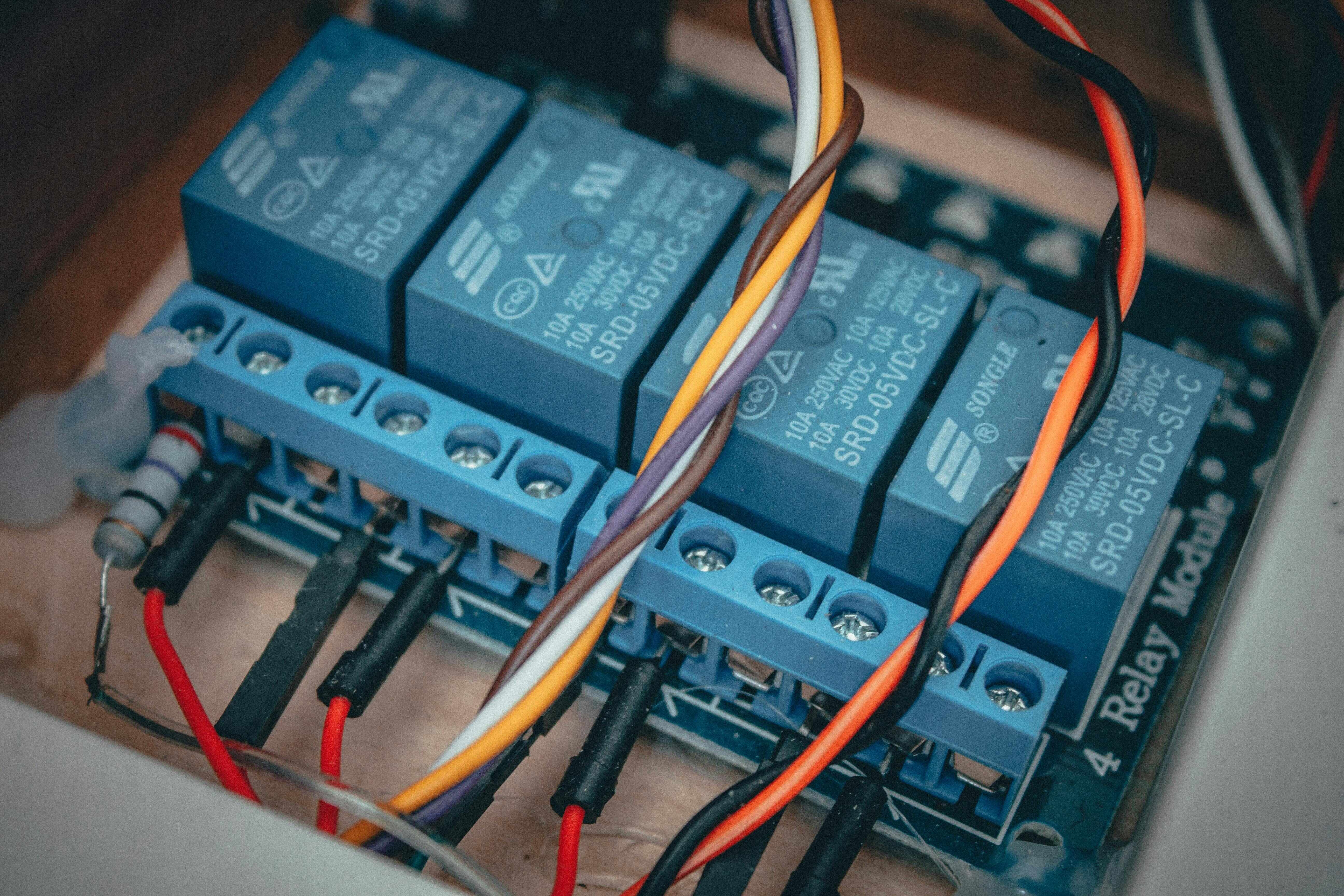
Let’s build a Smart IoT Relay Module to control a 220V AC lamp using an ESP8266-01 module and a 5V single-channel relay. This project allows remote control via a web server, making it ideal for home automation.
Components Required
- ESP8266-01 Wi-Fi module
- 5V single-channel relay module
- 220V AC lamp
- 5V power supply (USB or adapter)
- Jumper wires
- Breadboard or PCB
- Smartphone or computer for control
Circuit Diagram
-
ESP8266-01:
- VCC → 3.3V power supply
- GND → Ground
- GPIO2 → Relay IN pin
-
Relay Module:
- VCC → 5V power supply
- GND → Ground
- COM → Live wire of 220V AC
- NO → Lamp’s live wire
- Neutral wire → Directly to the lamp
Code Explanation (Line by Line)
-
#include <WiFi.h>– Imports the Wi-Fi library to use ESP32's Wi-Fi capability. -
const char* ssid,password– Stores your Wi-Fi network credentials. -
int RelayPin = 2;– Relay is connected to GPIO2. -
WiFiServer server(80);– Creates a server on port 80 (standard web port). -
pinMode(RelayPin, OUTPUT);– Sets GPIO2 as output. -
digitalWrite(RelayPin, LOW);– Turns relay OFF initially (assuming active-low). -
WiFi.begin()– Connects to your Wi-Fi. -
WiFi.localIP()– Prints the IP address of ESP32 for browser access. -
loop()– Continuously checks for new client (browser) requests. -
request.indexOf("/RELAY=ON")– Turns ON the relay when this URL is requested. -
request.indexOf("/RELAY=OFF")– Turns OFF the relay when this URL is requested. - HTML is dynamically sent as response to show ON/OFF status and clickable buttons.
Accessing the Web Relay Control
Once you upload the code and open the Serial Monitor (115200 baud), you will see something like:WiFi connected
Server started
Use this URL: http://192.168.1.120/
-
Turn On → Turns relay ON
-
Turn Off → Turns relay OFF
Applications of Relay in IoT Projects
- Home Automation (Light/Fan/Motor control)
- Smart Agriculture (Water Pump)
- Industrial Automation
- IoT-based remote switches
Where to Buy
Prices may vary. Click on "Buy Now" to check current availability and pricing.
Administrator
Frequently Asked Questions
Common questions about Ultimate Guide to Relay Modules for IoT: Complete Details and Setup Tips. Find answers to the most frequently asked questions.
User Reviews & Comments
Share your experience with this IoT Blog. Your feedback helps our community make informed decisions!
Share Your Experience
Help others by sharing your thoughts about this IoT Blog.
Related Blogs
Explore more IoT Blogs in the same category
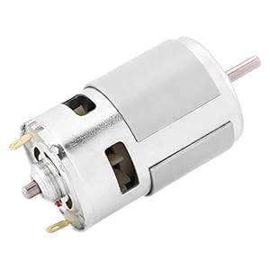
DC Motor in IoT: Types, Working, Applications, and Integration Guide
Output Devices
Discover how DC motors power real-world IoT applications. This complete guide covers DC motor types, working principles, benefits, and step-by-step integration for smart devices. Learn how to use DC motors in IoT projects with precision and efficiency. Ideal for developers, students, and IoT engineers seeking reliable motor control solutions.

Electromagnet in IoT: Working, Applications & Benefits in Smart Devices (2025 Guide)
Output Devices
Discover how electromagnets are transforming IoT technology with smart functionality, precision control, and energy efficiency. This guide explains their working principle, real-world applications, and benefits in connected systems. Ideal for developers, tech enthusiasts, and IoT project creators seeking advanced automation solutions in 2025.
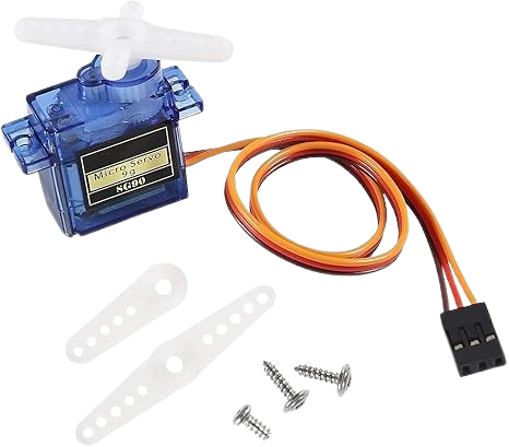
Servo Motor: Types, Working, Applications, and Complete Guide
Output Devices
A servo motor is a high-precision electromechanical device used for accurate control of angular or linear position, velocity, and acceleration. This complete guide covers its types, working principle, features, and applications across industries such as robotics, automation, and manufacturing. Learn how servo motors operate, their benefits, and how to choose the right model for your specific project or industrial needs.
No Reviews Yet
Be the first to share your experience with this IoT Blog!